
Introduction
I recently became interested in arcade history. Pinball history is particularly fascinating for the way inventors have come up with so many mechanical innovations over the years. From the first springer launch to the first speaking pinball to incorporating a wide variety of illusions, pinball remains something that simply can’t be replaced with virtual versions.
While investgating a 1972 Bally Time Zone pinball machine (also known as Space Time), I found an innovation that screamed 1970s. Check out the “portal” in the bottom center of this video:
Unable to fit an entire pinball machine in my home, I went for attempting to replicate this one part. With the popularity of the Maker Movement and easy-electronics development with the arduino, I decided to see how quickly I could replicate this piece with LED lights.
Thanks to the arduino’s programmable nature, I was able to set the center hole to randomly light six LEDs, making it a possible 1D6 role:
Parts
There’s about $100 of parts that went into the project:
- Time Zone Portal Piece: found on ebay for $25.
- Arduino UNO R3 Board: to
control the LED light sequencing. - 9V DC Wall Adapter: to power the arduino after taking it off USB power.
- Sunfounder Project Super Starter Kit for Arduino UNO R3: this is a great parts bundle with lots of LED lights, wires, a USB cable, and projects of increasing complexity that get you to controlling LEDs in patterns. It also comes with an LCD character display, buttons and lots of other toys for future projects.
- Tools: glue gun, crimper, crimps
- 3D-Printer or Black Cardboard: to put another circular cover on top of the pinball portal contraption.
Prototyping
Prototyping
Working through the online projects at the Sunfounder site, I started with a simple blinking LED light, flowing LED lights, and the RGB LED light to understand how to sequence and control individual lights on the breadboard.
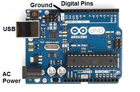
The arduino itself is very straightforward, really lowering the bar for entry into electronics experimentation. Aside from one issue where my computer failed to recognize the USB device and I had to manually go into the Windows device manager to load the drivers, I was up and running in about half-an-hour. Running electronics off the arduino is all about pluggin them into numbered digital pins shown below, running them back to the ground (GND), and then telling the arduino to feed electricity to those pins in the code.
Arduino
Each LED is pretty simple to light up. The only catch is that the two wires have to be plugged in the right way. If your LED doesn’t light up, take it out, turn it 180-degrees, and plug it back in.
Pin# > Breadboard Row# > Resistor (220?) > LED > Ground
You can see a diagram of this setup under the “Experimental Procedures” tab of the experiment on the Sunfounder’s site.
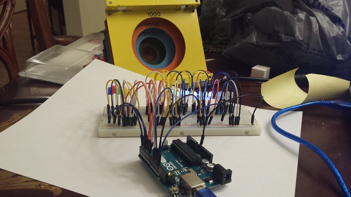
Here’s what the final prototype looked like running on the breadboard:
Coding
Here’s the ‘finalized’ code for the light sequencing. My comments explain what’s going on. Loading code onto the arduino is a lot of fun. It only takes a few seconds to compile and see your changes live in the electronics. I experimented with lots of different delays, effects, and sequences before finally settling on this one… and I’m already planning on changing it.
//PORTAl LED LIGHTS SEQUENCING
/**************************************/
//lowestPin and highestPin are for the four levels of
//the portal. There will be four lights in each of these.
const int lowestPin = 9;
const int highestPin = 12;
//Six different colored LEDs plugged into
//digital pins one through six.
const int lowestColorPin = 1;
const int highestColorPin = 6;
//How long to wait between turning LEDs
//on and off.
int rate = 800;
int uniquePins[0];
/**************************************/
//This is the code that runs when the arduino initializes.
//Here we register our LED pins as outputs.
void setup()
{
//set pins 9 through 12 as output
for(int thisPin = lowestPin;thisPin <= highestPin;thisPin++) { pinMode(thisPin,OUTPUT); //initialize thisPin as an output } //set pins 1 through 6 as output for(int thisPin = lowestColorPin;thisPin <= highestColorPin;thisPin++) { pinMode(thisPin,OUTPUT); //initialize thisPin as an output } } /****************************************/ //This function gets a random pin that hasn't been //selected before. int getUniquePin() { int newint; bool inarray = true; while(inarray) { newint = random(lowestColorPin, (highestColorPin+1)); inarray = false; for (int i = 0; i < sizeof(uniquePins); i++) { if (uniquePins[i] == newint) { inarray = true; } } } uniquePins[(sizeof(uniquePins)+1)] == newint; return newint; } //This function selects 1-6 pins and then calls //getUniquePin() to generate 1 to 6 random colored LEDs. void randomColor() { int numberOfPins = random(lowestColorPin, (highestColorPin+1)); uniquePins[0]; for (int i = 1; i <= numberOfPins; i++) { digitalWrite(getUniquePin(),HIGH); //turn this led on } delay(rate); for (int i = lowestColorPin; i <= highestColorPin; i++) { digitalWrite(i,LOW); //turn this led off } } //When the sequence starts to run very quickly, I switch from //randomly selecting LEDs to flowing through all the colors //in sequence. void sequenceColor() { for (int i = lowestColorPin; i <= highestColorPin; i++) { digitalWrite(i,HIGH); //turn this led on if (rate > 100)
delay(75);
else
delay(rate);
digitalWrite(i,LOW); //turn this led on
}
}
/******************************************************/
//Arduinos run their programs in this loop function.
//I play with the
void loop()
{
//iterate over the pins
//turn the led on from highest to the lowest
for(int thisPin = highestPin;thisPin>=lowestPin;thisPin–)
{
digitalWrite(thisPin,HIGH);//turn this led on
delay(rate);//wait for 100 microseconds
digitalWrite(thisPin,LOW);//turn this led off
}
//Do the random color while the delay rate is long
//enough for a human to see what lights lit up;
//otherwise, run through the colors in a sequence.
if (rate > 200)
randomColor();
else
sequenceColor();
//Every cycle, decrease the delay.
//Because shorter delays don’t run as long,
//decrease how much we decrease the delay at
//certain points to draw out how long it plays
//at that speed.
if (rate > 600)
rate -= 50;
if (rate > 400)
rate -= 25;
else if (rate > 200)
rate -= 10;
else if (rate > 100)
rate -= 2;
else
rate -= 1;
if (rate <= 0) { rate = 800; } delay(rate); } [/ccie_java]
Assembly
Finished Product
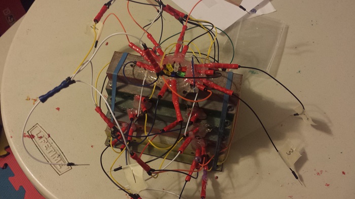
Going from the breadboard to the real thing was quite tedious, and easily the longest part of this effort. One lesson I learned very quickly was to test every connection twice before crimping. Statistically speaking, I probably got my LED connections backwards more than 50% of the time thanks to Murphy’s Law. Hot glue placed the lights in the device. The most questionable part of this was feeding every LED back to the ground. I wasn’t sure how to properly feed all the LED wires back to the ground, so I crimped all the ground wires together into oa single wire.
The end result is a wiring mess, but a wonderful display:
And the best part is: when I get tired of it, I can reprogram it.